Introduction:
The aim of project is to re-engineer a remote control car to autonomously navigate through a track by detecting lanes and centering itself between them as well as detect objects in front of it and avoid collision. The RC car detects lanes through image input from a low-resolution camera mounted at its front. Using an IR distance sensor, the car determines when to stop accelerating once a certain distance between a forward object has been breached. All computations based on sensor data are handled by an Atmel Mega644 MCU. Due to the nature of the input peripherals, especially the camera, this system is extremely time sensitive so that computations had to be optimized as much as possible in order for the car to be able to react and respond with proper movements in real time. In addition, given the limited computational capacity of this 8-bit MCU, our design made use of several computational efficiency strategies.
Circuit Diagrams:
MCU Interface Circuit:
 Power Circuit  Optoisolator DC Motor Control Circuit: 
H-Bridge Circuit: 
Logical Design:
Rationale of Project Idea: The basic idea of our project stemmed from a rather playful interest in using an MCU to program a robot to perform some common everyday function autonomously. Given our lack of mechanical engineering expertise, an RC car was chosen as the hardware to be programmed since it provides all the components and infrastructure necessary for a simple mechanical system, all at a low cost with an easy-to-use interface. We decided to design the car so that it would automatically navigate a track made of parallel lines which were meant to mimic the roads that actual full-sized cars encounter. Given that there has been some societal interest in the development of automatic driving car technology, we figured that designing a low complexity system with this functionality would be an exciting and practical project to pursue. Perusing through past ECE4760 final projects helped give us tips on how to approach our own project. The Line-Following Car of Spring 2007 uses photosensors to guide the vehicle along a single line track. Our original concept intended to use a low resolution camera as the input tracking device instead. Given the similarities in our projects, we were even more inspired to give our RC car the functionality of detecting a two line track and stay within the lane, which requires a more complex algorithm than a single line track follower. The Autonomous Self-Parking Car of Spring 2009 introduced us to a cheap, tractable IR distance sensor component that we later incorporated into our own design as a way to detect forward objects and avoid colliding with them. Logical Structure Our high-level hardware design consists of seven main blocks as shown in the block diagram. 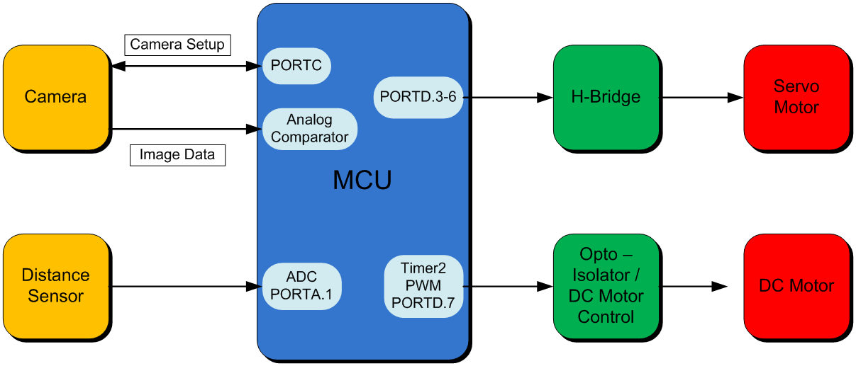 All computations and processing are handled by the ATMega644 MCU. The MCU receives inputs from two peripherals the low resolution CMOS image sensor(camera), and IR distance sensor. Image input in the form of a 128x123 pixel array is processed in the MCU using the internal analog comparator, turning pixels that were originally represented by bytes of data into pixels now represented only by bits. Since our RC car only has to detect the image of a road line in contrast to the rest of its environment, this binary pixel representation is sufficient for this purpose and saves immense amounts of computation time. The voltage threshold for the analog comparator had to be adjusted to a proper value for a given road line color which we chose to be black. Processing of this image input from the camera is done by the MCU to generate signals that indicate whether the car should turn left or right or go straight. These command signals eventually control the servo motor on the RC car that allows it to turn left or right, but must first go through an H-Bridge circuit so that polar voltages can be created to drive the servo motor in both directions (since the MCU cannot generate negative voltages). The MCU also receives an analog input from the distance sensor which is processed with the MCUs internal ADC into an 8-bit value. This digital value can be mapped to an actual distance, but is not done in software since it would be unnecessary and would only add more computation time to an already time sensitive system. The 8-bit digital distance value is used in a simple control algorithm that determines the duty cycle of the PWM coming out of Timer2. The PWM controls the operation of the cars DC motor, supplying the motor with a higher voltage when its duty cycle is higher. The PWM is sent to a motor control circuit that is implemented using the same design as the control circuit from Lab 4 which uses an optoisolator to separate the MCU circuitry from the motor circuitry. The optoisolator is necessary so that excessive current draws from the motor do not damage the MCU hardware. We decided to only have the car move forward; therefore, a circuit like an H-Bridge was not required to operate the DC motor and only had to be driven in one direction. To power all of our hardware, several power sources had to be used. The target board for the MCU required a 9V battery for proper operation. Combined with the 5V regulator on the board this provided a constant 5V Vcc to the MCU. The camera was powered using the 5V supply on the MCU and since it required a minimal amount of current, this setup posed no problem to the system. The distance sensor is powered from a different battery source a battery pack consisting of three AA batteries in series at 1.5V each. The grounds of both this 4.5V battery pack and the MCU were tied together so that the analog voltage output of the distance sensor had a ground reference. The rest of the circuitry is properly isolated from the MCU and is powered from the cars battery setup which uses five AA batteries rated at 1.5V each for a 7.5V total supply. This served to be too much for the H-Bridge circuit which requires less of a voltage. To remedy that, diodes were placed in series between the positive terminal and the H-Bridge Vcc pin to drop the voltage instead of using an additional battery source. Our high-level software design consists of three main functions as shown in the block diagram initialization, image processing and control, and distance sensing and control.  All software computations are done by the MCU using a 20MHz base clock. The initialize routines initiate the MCU I/O ports, timers, PWM driver, and ADC for general program operation and peripheral interfacing. The main loop of our software continuously cycles between the distance sensing and image processing control but skips image processing if the distance sensing code determines that the car should be stationary since capturing more images when the car should not be moving is unnecessary.This means that the software does not enter either of these functions with a set frequency but rather proceeds through the loop continuously so that the functions are called as soon as the CPU is free to make the computations. The distance sensing control involves reading a converted ADC value and controlling operation of the DC motor through adjusting a PWM duty cycle. At some threshold digital value that corresponds to a forward object being too close, the software will set the PWM duty cycle at a low value to stop the DC motor from turning. If that distance threshold is not reached, the car undergoes normal operation and the PWM duty cycle is set so that the car moves at a slow pace to allow for more effective response time by the image processing control. However, if the car is stationary, meaning that its previous PWM duty cycle is low, in the next distance sensing loop the software will jump start the car with a higher-than-normal PWM duty-cycle that only lasts for one cycle. This is necessary to combat friction that prevents the normal operation PWM duty cycle from starting the car. The jump start functionality was required since we did not want the car to move so fast during normal operation. The image processing control stage begins with setup of the camera since the image sensor hardware requires parameters to be set before its image capture functions can begin operation. Image processing begins with reading image input from the camera. To interface with the camera properly, the camera hardware is clocked at a rate specified by the MCU which is set with a period long enough for the MCU operations to store a pixel of image data in an array. Once the camera begins output of its image data to the MCU, the process cannot be interrupted else the image data array will be corrupted since the camera outputs its data continuously until it is finished. Thus, no interrupt service routines besides the one that generates the clock rate are used in our entire software. After the camera is set up, it continuously takes pictures and sends an ordered list of pixels to the MCU. This is fed into the MCU�s internal 1 bit comparator, and is converted from a analog signal to a 1 bit black or white value. We store this 1 bit pixel in an optimized array called picture[], and parse the proper lines to detect where the road lanes are. Once we find the lanes and determine the center of the lanes, we determine the proper turning condition. The result is used to control the H-bridge IN1 and IN2 inputs, which in turn control the steering of the car. The three task are continuously repeated. Hardware Design: 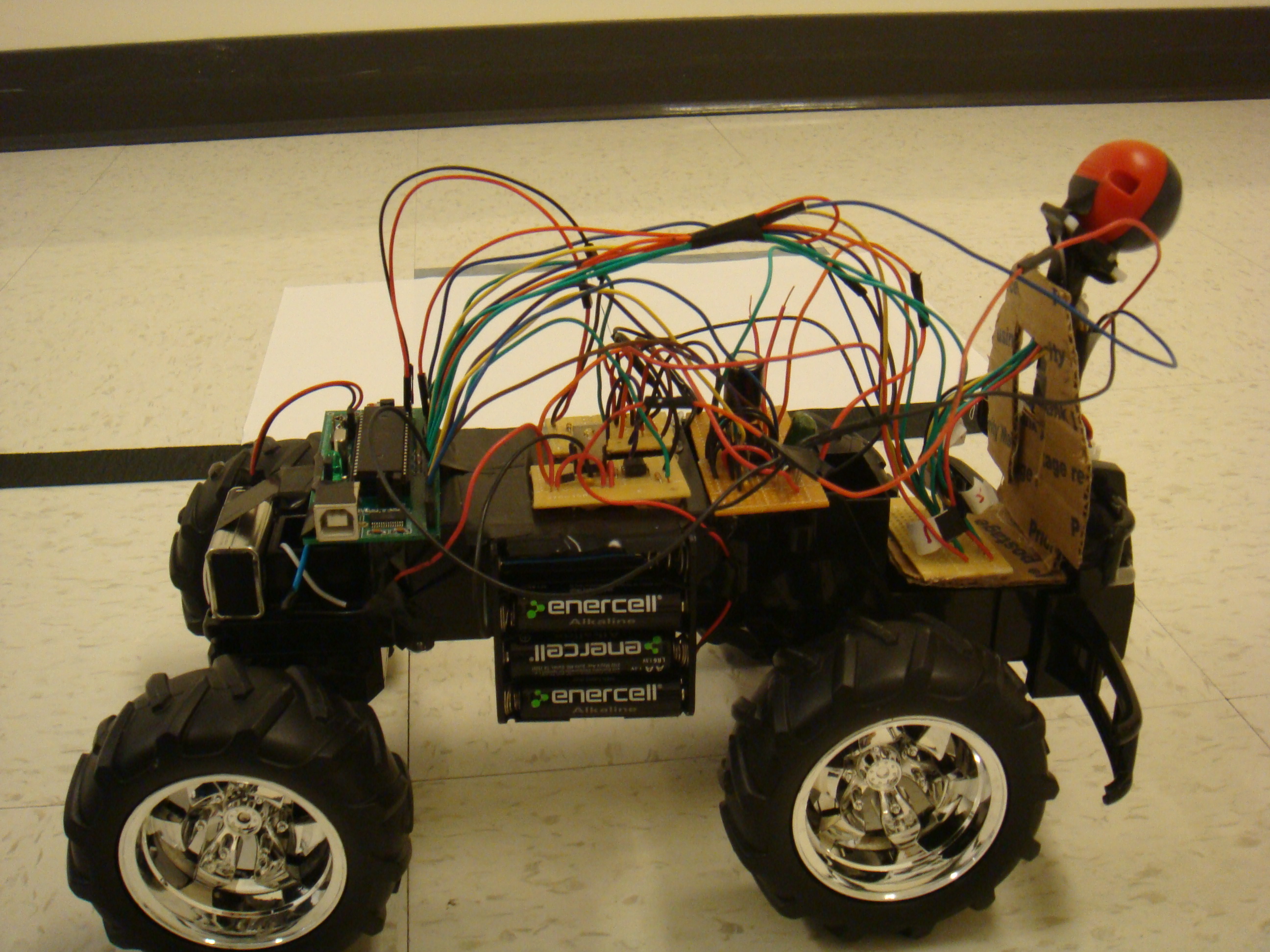 Due to the low cost and relatively low complexity of our design, this project can easily be rebuilt by those interested in tinkering around with an RC car. The following sections describe the hardware that is used in detail and explains how they are set up.
Hardware Details
Remote Control Car: The RC car used in our project was the cheapest RC car we could find at our local Radioshack. It is a 4-wheel car with rear-wheel drive and front-wheel steering. Since a datasheet for the hardware was not provided with it, we had to manually test the cars connections and figure out how to properly operate its motor functions ourselves. Given the nature of our project, the RF functionality of the car was scrapped and the receiver board on the car was removed. Only six wires had to be tested to determine their function - two wires for the car battery, two wires for the rear-wheel DC motor, and two wires for the front-wheel servo motor. The voltage across the car battery hovers around 7.5V, which was expected since the car requires five AA batteries rated at a nominal 1.5V each. To test the servo motor wires, we applied different voltages across it starting low and incrementing the voltage until a turning response by the motor was achieved. The servo motor turns in one direction with a positive voltage across it, and turns the other direction with a negative voltage across it, but does not have the capability to turn at varying angles. The servo motor begins responding at around a 3.8V threshold but reaches the max turn angle at a much slower rate. Applying a larger voltage across the motor causes the motor to reach the set turn angle faster. Measurements were taken to determine the effect of varying voltages across the DC motor. Using parts of the tachometer circuit that we built in Lab 4 for this class, we were able to get a relatively accurate measurement of the car�s wheel RPM for a given DC voltage across the motor. The data gathered shows us that the threshold voltage for the DC motor to power actual motion of the wheels is around 1.3V and that the voltage-to-RPM relationship is linear. Distance Sensor: The Sharp IR sensor (GP2Y0A21YK) that we used is a very handy, cheap, and easy-to-use piece of hardware that can measure distances in a range from 10 to 80 centimeters. The sensor only has three connections that need to be interfaced with � power supply, power ground, and its distance output. Given a supply voltage optimally between +4.5 to +5.5 volts, the sensor outputs its measurement of distance as an analog voltage between 0V and 3.1V as shown in. 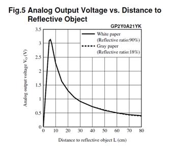 Powering the Distance Sensor: Powering the Distance Sensor:After several different attempts and methods of powering the distance sensor, we decided at last to use three AA batteries in series at 1.5V each for a total of +4.5V to power it. Since we found that the distance sensor drives a lot of current (typically 30mA), powering it off of the MCU posed problems to reliable MCU operation. In addition, we found that connecting the distance sensor across the power lines of the MCU introduced a lot of noise to the camera�s operation since it too is powered by the MCU�s power lines. Thus we ended up using another power source in the three AA batteries. However, the distance sensor output needs a common ground in order for the MCU to interpret the data correctly. The grounds of both the MCU and the 4.5V battery pack were thus connected so that distance sensor could be properly interpreted. This sort of unfavorable connection in theory could cause random and unexpected behavior, but since our system worked when tested, we decided to go along with it due to time constraints. ADC Hardware Setup: The analog output of the distance sensor is fed directly to the ADC that is internal to the MCU through PORTA1. Since the distance-sensing functionality has much lower priority than the image sensing functionality, our setup of the ADC hardware and the calculations using the resulting digital value were optimized to use the least amount of computation time possible. The ADC successive approximation circuitry requires an input clock frequency between 50-200kHz for maximum resolution. In our case, a higher frequency clock rate could have been used since we only make use of 8-bit resolution. But for safe measure, we used a clock prescaler of 128 on our 20MHz base clock for a resulting 156.25kHz ADC clock. Since a normal ADC conversion takes 13 ADC clock cycles, this meant that the average ADC conversion time is near 83.2 microseconds. For the ADC reference voltage, we chose to use the internal 2.56V generated by the MCU. This value was chosen because of convenience and because based on the output voltage vs distance curve of the sensor, a 2.56V value corresponds to a distance around 9cm which is at the edge of the operating limit of the sensor and is a small enough distance that the car should know to stop anyway. The ADC is capable of providing a 10-bit result. However, our system did not require that degree of accuracy and used only the higher 8 bits so that the of the two registers that hold the ADC result, only the high register had to be read which saves some computation time. To do this, the command for the ADC to left adjust its result had to be set in software. The resulting ADC conversion that we read from the high result register, ADCH, follows this formula: ADCH=(V_in*255)/V_ref Where Vin is the input coming from the distance sensor and Vref is the internal 2.56V value. The range of values of ADCH are thus between 0 and 255. We tested to see whether or not a Vin greater than 2.56V would be a problem but found that voltages greater than Vref resulted in an ADCH value of 255 which does not pose any problems to our system. Since as much computation time had to be conserved for the image sensing software, sampling from the ADC was not periodically triggered and had to be manually started in software. More detail on the distance sensing software is discussed in a different section.
Motor Control Circuit:
Our circuit that controls operation of the car�s DC motor uses the same design as the motor control circuit that we used in Lab 4 for this class. We created a PWM using Timer2 Output A out of PORTD7. The duty cycle of the PWM eventually determines the voltage that is applied across the DC motor. The PWM is sent through a 4N35 optoisolator in order to isolate the MCU power lines from the DC motor and avoid damage of the MCU hardware from excessive current draws by the motor. A capacitor and a 1N4001 diode are connected in parallel with the DC motor to improve noise resistance and inductive switching spikes on the motor, respectively. The isolator circuit is powered by the car battery which serves as Vcc and GND as shown in the schematic  To get a sense of the level of impact that the PWM has on the motor, we measured the voltage across the DC motor for a given OCR2A value (which controls the duty cycle of the PWM). The results are shown: 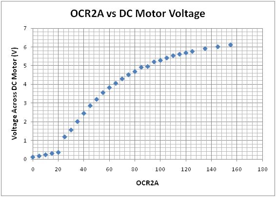
H-Bridge Circuit:
To operate the servo motor correctly, we needed to generate both a positive and a negative voltage so that the motor can undergo both right and left turns. We chose to buy a premade H-Bridge IC that provides us with this ability along with several safeguards that protect the hardware from damaging itself. The Toshiba TB6549PG is a relatively economical H-Bridge IC that uses MOS transistors to carry out its functions. The H-Bridge can take a supply voltage up to a max of 30V. The magnitude of the supply voltage is reflected across the output lines OUT1 and OUT2 of the H-Bridge when it is in the modes that correspond to turning the servo motor left or right. The H-Bridge takes four additional inputs that our MCU provides through PORTD which are command signals that specify which mode of operation the H-Bridge IC should be in. The PWM signal is an optional signal that can be used to periodically alternate what mode the H-Bridge is in. When use of this signal is not needed the input should be driven high at 5V which is what we did in our system. The Standby signal (SB) when driven low (~0V) turns off all other circuits in the H-Bridge. Our system does not make use of this functionality and constantly drives this signal high at 5V. When driven at differing digital voltages, the IN1 and IN2 signals control whether the H-Bridge output is positive or negative Vcc. For our system and for the way that we wired our servo motor to the H-Bridge, having IN1 high at 5V and IN2 low at 0V causes the car to turn right, and the reverse setup causes the car to turn left. Proper operation of the H-Bridge required additional components to be used. A capacitor across pins Vreg and S-GND is connected to prevent oscillation at the internal 5V power supply of the circuit. Two capacitors, one connecting pins CcpB and CcpC and the other connecting pin CcpA to S-GND, are required for the H-Bridge�s internal charge pump circuit. A power supply capacitor is also connected across pins Vcc and P-GND. For the servo motor, both a capacitor and resistor are connected in parallel with it to reduce noise and limit current, respectively. Powering the H-Bridge: From our manual testing of the RC car�s servo motor, we found that a voltage greater than approximately 3.8V was able to turn the actual motor in a direction. Since the voltage across the output pins is determined by the supply voltage to the H-Bridge, we wanted the supply voltage to be in the range of 4-5V for reasonable turning operation. We wanted to avoid introducing a new battery power source and since the MCU power source is out of the question due to the need to isolate the MCU from the servo motor, the car battery was used to power the H-Bridge circuit. However, since the car battery is rated at 7.5V, several diodes were placed in series between the car battery and the H-Bridge supply voltage pin to drop the voltage to an acceptable value. Dropping the voltage from 7.5V was necessary since and excessive voltage applied across the servo motor caused mechanical strain and produced a clicking noise as the car attempts to turn more than it can. In fear that this strain would damage the RC car, we made sure to add the diodes in to reduce the voltage. Camera The Mitsubishi M64282FP Image Sensor is a 128x123 pixel CMOS camera that outputs an analog signal. We are using this camera to detect black lines on a white background, so we want to use the camera to take a picture of the lanes and store the image taken into our MCU and do calculations on this data. In order to do that, we have to first understand how our camera works. Overall, the camera functions as follows. 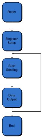 First, the camera needs to be reset by the RESET input. The camera then needs its registers within the camera chip to be set up by the SIN and LOAD inputs. After that, the camera will wait for a start signal to start sensing the image (start taking a picture). The START input initiates the start signal that is internally inside the camera and this start signal will continue to assert itself accordingly. After taking a picture, the camera will output the data to the Vout output. The camera will keep taking pictures until the camera is turned off. Now, we will go into more details about these stages and important signals involved.
Xck
Xck is the camera clock and it is an input. It has a maximum frequency of 500kHz and does not have a minimum frequency. For our convenience, we set the clock to 25kHz. We chose this frequency since we need a fast enough clock so that we can obtain data from the camera fast enough to determine the turning of the car accurately but we also need a slow enough clock speed to have enough time to convert the output into a desired format before the next data becomes available. After some testing, we found that 25kHz is sufficient.
Reset The RESET input triggers reset in the camera. This signal is active low and is detected at the positive edge of the camera clock, which is also an input. Register Setup
There are 8, 8-bit registers on the camera chip that represent 13 different registers. The positions of these 13 different registers within the 8 physical registers are defined below. 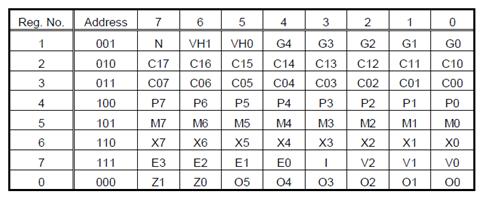
Pg. 9 of Datasheet
These registers determine how the camera operates. It basically set up different settings for the camera to operate in different modes. We do not need the functionality of many of these registers so we will only explain the ones that are important to us later in the interfacing section. For now, let�s focus on the camera signals involved and what they do. The input signal SIN is used to set the registers to their correct values and the input signal LOAD is used to signal to load the inputted register values. SIN signals are detected at the positive edge of the camera clock (Xck), which is another input. The register values will not be set until load is detected at the negative edge of Xck. The SIN signal sends in each bit of the register value and the load signal is asserted every time after we finish sending the bits for one register. Since we have 8 registers, we do this 8 times and load is asserted 8 times. The following 2 timing diagrams from the datasheet clarify what is happening. 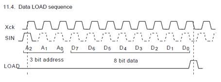
Pg. 9 of Datasheet. Loading one register.
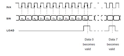 Pg. 16 of Datasheet. Loading all the registers. Pg. 16 of Datasheet. Loading all the registers.As shown above, we need to send the address bits of the registers one by one first and then send the 8 data bits before we assert the load signal. This is repeated until all the registers have been set. The camera requires that we set the registers before we start taking a picture, but these registers can also be set simultaneiously during image capture. Start and Data Output After setting the registers, the camera will wait for the START input to be asserted to take a picture. The camera detects the START signal at the positive edge of Xck. After the camera detects the start signal, it will output the image data on Vout output and assert READ output after the exposure time, which is one of the settings we have to set in our registers. While the READ signal is high, the camera will output each pixel of the frame on the positive edge of each clock cycle from our Xck. After the camera has outputted the whole frame, the READ signal will be low again and after 5 clock cycles, the internal start signal within the camera will be asserted and another picture will be taken and the whole cycle starts again. The following timing diagram from the datasheet shows this occuring. 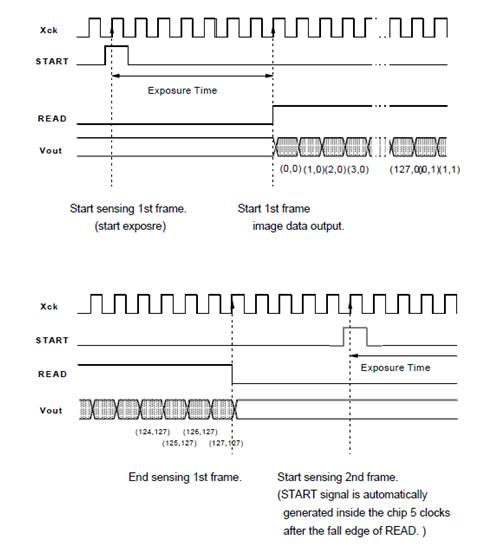 Pg. 17 of Datasheet Pg. 17 of Datasheet
Interfacing with the Camera:
We obtained the Mitsubishi M64282FP Image Sensor from the GameBoy Camera, which Rick�s parents had found lying around the house. We found a few old websites that people had wrote up explaining how they incorporated the GameBoy Camera onto their robots. These websites were very helpful for understanding how to interface with the camera and how the camera functions. After dissecting the camera we extended the wires and got something that looks like this. 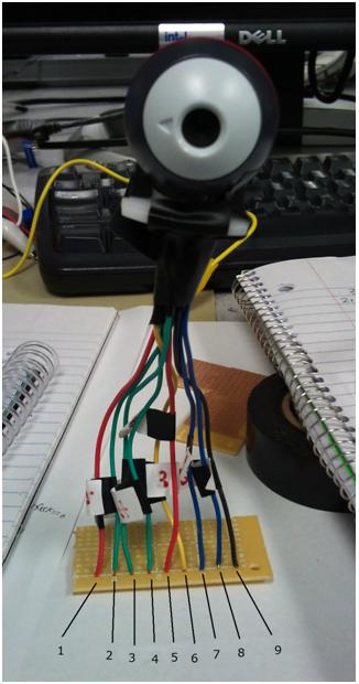 For simplicity, we decided to keep the camera head intact and soldered wires onto wires coming out of the camera. Luckily, one of the website has defined for us which pins to the camera these wires corresponds to. We connected these wires to the following ports on our MCU. Wire Name Direction to Camera Use Mega644 Pin 1 VCC Input Power VCC 2 START Input Start taking a picture Port C Bit 2 3 SIN Input Input Data Port C Bit 3 4 LOAD Input Set input data Port C Bit 4 5 RESET Input Reset Port C Bit 5 6 Xck Input System clock Port C Bit 6 7 READ Output Read data Port C Bit 7 8 Vout Output Analog pixel output Port B Bit 2 9 GND Input Ground GND We have described the timing and function of all these inputs and outputs of the camera in detail previously in this section. We connected the camera power and camera ground to the MCU power and ground since the camera needed a 5V power which the MCU can provide. The Xck camera clock is driven by the hardware clock controlled by an ISR on the MCU. The START, SIN, LOAD, and RESET signals are controlled by software functions to give the correct values at the right time. In general, we allocated most of Port C to the camera. We want to use this camera to take a picture of the road to detect lanes. More specifically, we wanted to detect black lines on white floors on our camera. To do so, we need to convert the analog output of our camera into a digital one. In order to save space in our memory (since we only have 4KB of memory) and to utilize the Mega644 board as much as possible, we decided to put the output of the camera, Vout, to Mega644�s internal analog comparator and compare Vout with 1V. Note that this 1V values is picked arbitrarily between 0 and 5V since the camera output can be adjusted accordingly and since the camera outputs are quite unstable depending on what parameters we give it. We decide to have a constant circuitry and change the camera settings through software when needed. Our comparator produces a 1 if our Vout output from the camera is above or equal to 1V and a 0 if Vout is less than 1V, which is a 1 if the pixel is white and a 0 if the pixel is black. This 1-bit output would save a lot of space. With our 128x123 camera, it will take 1968bytes to store an entire picture, which is more than enough since we only need enough room to store one picture and minimal storage space for other variables. To do all of this, we need to be able to provide 1V for our analog comparator. Since we only have a 5V supply from our MCU, we need a voltage divider. The circuit is shown below. 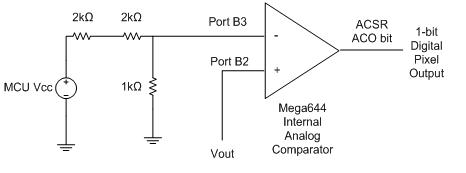 We used 2 2KOhm resisters and 1 1kOhm resistor to build our voltage divider. Since the power coming from our MCU is constantly 5V, the voltage divider will constantly output a 1V into the comparator, which is Port B Bit3. Vout is inserted into Port B Bit 2 to be compared to 1V, producing a result in the ACO bit of the ACSR register. Using the READ signal coming from the camera and our hardware generated Xck, we use software to store the value coming out of the comparator accordingly. A thing that we have not yet mentioned is the register values for the camera. The camera has many different modes of operation such as positive and negative output, horizontal and vertical edge detection and extraction, 1-D filtering and any combination of these modes. These different modes determine how the picture is taken and affect the output of the camera. The modes are determined by 13 registers of varying sizes that we have to set to initialize the camera and they are grouped into 8, 8-bit registers on the chip. The datasheet also provides a table with typical register values in different modes. We really do not need any of these extra functionalities of the camera, so we decided to use the simplest mode possible, which is the positive output mode. The following is the typical register values for positive output mode. 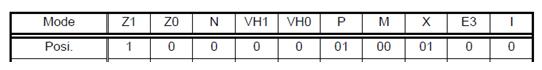 Pg.14 of datasheet Pg.14 of datasheetThis table only defined 7 of the 13 registers that we need to set. So we needed to look into the other 6 registers and determine values for them. The E register is the enhancement ratio register. We set this to 100% since we did not want any enhancement. The O register adjusts the offset level of the signal voltage and we set this to 0. The V register determines the output voltage reference and we set this value to 0.5V. G is the gain register and we set it to 24.5dB. The O, V, and G values are determined by testing the output voltage of the camera manually. We adjusted these register values until we found something that we can work with. In general, we wanted a relatively high gain to make it easier for us to differentiate between the light and the dark. We wanted to compare this output with 1V so we probed the output of the camera to see what register values would produce a signal that has a mean of about 1V. The C0 and C1 registers determined exposure time. We realized that this register value varies depending on the brightness of the room and needs to be changed accordingly every time the car moves to a spot with different lighting. We realized that our camera is extremely sensitive to light. This restricts the car to run in a track with consistent lighting and the car will require adjustments every time we change locations. We tried using software to adjust the lighting while the car is running but this proved to be very difficult since our algorithm runs in a way that a lane doesnt have to always be detected. Having a car that can run while adjusting the lighting settings might be feasible if we change our algorithm to always detect at least one line, but due to many constraints such as the width of the car and the range of our camera, we cannot. Since we have not found a solution to this problem yet, we decided to restrict the car to run on a track with constant lighting.
Power Circuits:
Our final design uses three battery sources to power all of our components as described in the sections above. A 9V battery powers the MCU which in turns powers the camera through its 5V supply line. The distance sensor is powered by a 4.5V battery pack consisting of three AA batteries placed in series with its negative terminal connected to the MCU ground to give the distance sensors analog output a ground reference for proper ADC conversion. The circuitry that powers both the DC motor and servo motor of the RC car is powered by the cars 7.5V internal batteries which consist of five AA batteries. Both the 9V battery and the 4.5V battery pack are strapped to the sides of the RC car using electrical tape. An additional power board was created to more easily interface the power lines from the MCU and car battery with the rest of our hardware.
Hardware Issues / Hardware Design Tradeoffs:
Powering the Distance Sensor: We had many problems with powering the distance sensor which we deem is largely due to the current draw of typically 30mA that is relatively much higher than our other hardware besides the motors. At first we decided to use the MCUs 5V power lines to power it since the distance sensor operating power supply voltage is between +4.5-+5.5V. The high current draw caused a loss of power to the MCU which led to the MCU resetting continuously. To remedy this, a large capacitor at around 330uF was placed in parallel with the MCU power lines. This solved the issue with power to the MCU and the distance sensor worked properly. When we began integrating the camera to our system, however, because the camera too is powered off of the MCU power lines we found that the distance sensor was still introducing some noise that made it impossible for the camera to accurately capture images. We then decided to add another battery source to get rid of this noise issue. In order for the distance sensos output to be interpreted correctly, however, it needs the MCU reference ground so the negative terminal of our distance sensors battery source was connected to MCU ground. In theory, this setup could have presented unexpected errors in our system, but since it worked after testing, we did not delve further into the issue.
Battery Power Loss: Using batteries while testing our system for extended periods of time proved difficult at times since as the voltage across the battery terminals deteriorated over time, our system behaved differently than expected unless it was recalibrated. In particular losses in power from the sources that power the MCU and the motors caused much frustration since we often misinterpreted it has problems in our hardware design or damage to our circuitry. In the end, however, being aware of this issue and having a voltmeter on hand made this issue less of a problem.
Lighting: It was discovered quickly when working with the camera that proper lighting made a huge difference in the accuracy of the cameras image capture functionality. Inconsistent lighting or off-colored tiles on the floor initially gave us much trouble when testing our turning algorithm. To fix this, light exposure parameters could be adjusted on the camera to operate accurately in the given environment. In the interest of time, we could not give the car the capability of adjusting its light exposure autonomously. Instead, the lighting issue must be handled manually for the given area that it is tested on.
Road Material: Another issue related to lighting arose when testing our system. Initially we had used tape to layout the road lines that our car was to maneuver between. However, the glare from the tape material caused inaccurate readings by the camera and prevented the system from working properly. A material that was dark and had no glare was required for proper system operation. Our cheap solution was to use a dark paper material and tape it down to form our track.
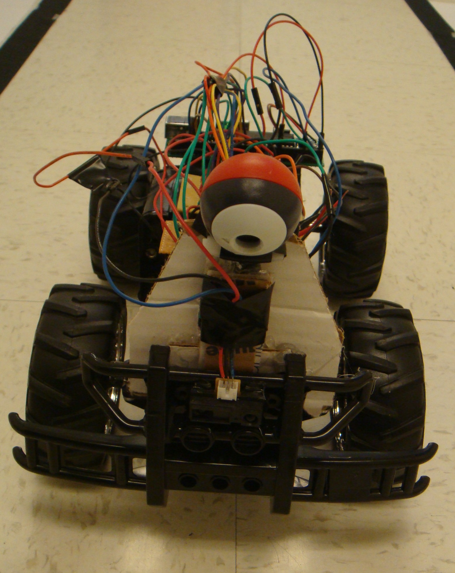
Camera Angle: The camera in our system is mounted on the front of the car facing straight ahead and tilted slightly downward to detect road lines in front of it. The angle at which the camera turns to the ground is not arbitrary and had to be adjusted to fit the systems image capture and processing software. If the camera is tilted too far to the ground it is impossible for the camera to see any reasonable length lane, but if it is not tilted enough the cameras scope is too far ahead and cannot detect areas close enough to the car causing the car to react to a situation that is much farther ahead of it. Lots of testing was done to find an appropriate camera angle to use.
Software Design:
Distance Sensing Control:
All of the distance sensing code is contained within a function called speedTask(). The function begins by writing to the ADC Start Conversion bit (ADSC) of the ADC Control and Status Register A (ADCSRA) to sample the analog input from the distance sensor and begin a conversion. The ADC takes 13 ADC clock cycles to complete a conversion during normal operation. With our 20MHz clock and a prescaler of 128, the ADC clock runs at 156.25kHz. The conversion time required is thus 83.2us. To ensure proper operation of the ADC in speedTask(), a hardware delay is implemented right after the conversion begins. After the conversion is complete, the high byte of the ADC result that is stored in register ADCH is compared to a threshold value which determines whether the car is too close or not. The value in ADCH ranges from 0 to 255 with higher numbers meaning that a forward object or obstacle is closer. The control algorithm is a simple if-else construct that contains three different conditions. If ADCH is greater than the threshold value, meaning that the car is too close to something, the PWM duty cycle is set to a value(stopDrive) that stops the car and a flag is set that tells the rest of the program that the car is stationary. This flag is cleared in the other two conditions. If ADCH is not greater than the threshold and the current PWM duty cycle is too low, the PWM duty cycle is adjusted with a higher-than-normal value(jumpDrive) that is intended to jump-start the car from its stationary state. If these two conditions fail, then the car undergoes normal operation and the PWM duty cycle is set to its normal operation value(normalDrive). All of these values ADCH threshold, stopDrive, jumpDrive, and normalDrive had to be fine tuned adjusted repeatedly in order to find the desired system response. These values proved difficult to calibrate at times when the battery sources we were using dropped in voltage over time.
Camera
We use software to generate a lot of our input signals to the camera: Only Xck is generated by hardware; the rest are generated by software. Most of the camera functions are used to generate input signals to the camera for initialization and has nothing to do with the main bulk of our program. Of the camera functions, only the function camRead, a function that reads and records the output from the comparator, is in the main bulk of the program. We used state machines for many of these functions to assert and lower registers at edges of our hardware clock. We know for sure that the timing of these state machines are correct because the camera clock speed is slow enough so we have enough time to produce the inputs to the camera accurately. In general, the camera functions cannot be interrupted so there are no interrupts in our code except for the generation of the clocks. We tried using flags instead to implement this but it turned out way too complicated and contained many coding errors. In the end, we got our state machine implementation to work so we decided to stick with this implementation. The flag implementation would probably have saved us a lot of computation time, but computation time is not a huge issue in our project so to us the best design is the one that works.
Picture Array
In order to store the 128 by 123 pixel camera image on the MCUs memory, we had to compress each pixel from a byte of data, with information about the intensity, to a single bit, which represented only black and white. With this compression, we created a 1968 element char array, where each array element held the information of 8 adjacent pixel bits. The array only takes about 52% of the MCUs memory, leaving more than enough memory for the rest of the storage required by our code. Unfortunately, the optimization requires a bit more logic for storing and retrieving pixel information.
storePixel
The function storePixel() stores a single pixel bit in the correct picture array element when given the proper x and y locations of the pixel from the camera Vout input. The array is organized as followed. Each horizontal picture line spans 16 consecutive array elements. Since each element stores 8 pixels, 16 elements stores 128 pixels appropriately. In order to store the entire picture, we need 123 lines, or 123*16 = 1968 bytes, or array elements. Therefore, to store a pixel, the function requires as inputs the pixel data, the x location, and the y location. Based on the x and y locations, storePixel() calculates the appropriate array pointer and shifts in the pixel data into the proper position of the elements byte of data.
getPixel
The function getPixel() returns the desired pixel value when given the proper x and y locations of the pixel from the camera Vout input. Based on the x and y locations, getPixel() calculates the appropriate array pointer and returns the pixel data at the proper position of the elements byte of data.
camReset
The function camReset is used to reset the camera. The RESET input from the camera requires that we have an active low signal that is detected at the positive edge of the camera clock Xck. We generated another clock halfXck in our ISR for changing signals between edges of the camera clock so that the camera can detect them at the edges of the camera clock. So using the halfXCK, our camReset function works as follows. 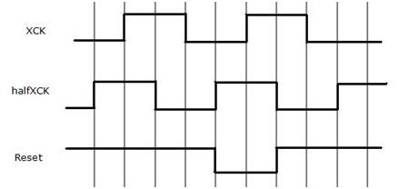 As shown in the timing diagram above, Reset is lowered when halfXCK is high and set back to high when halfXCK is low. We can see that this ensures that the Reset signal will be seen at the positive edge of XCK. The following is our actual state machine for this function. 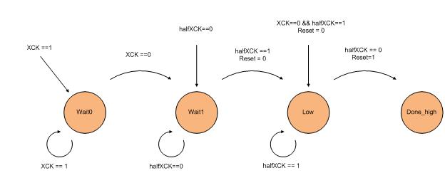 Basically, we want to set the reset signal low either at positive edge of halfXCK or right before the positive edge of XCK when XCK is 0 and halfXCK is 1 and we want to set it back to high at the negative edge of halfXCK. So before we lower the reset signal, we will wait in either Wait0 or Wait1 to wait for the positive edge of the clock. We change the signal Reset while we are changing states to ensure that it is consistent with our timing. We will then wait in the Low state until the negative edge of halfXCK and then set the reset signal high again.
setCamReg
The function setCamReg is used to set our registers. It takes an array of register values as the parameter and sets the SIN and LOAD inputs to the camera based on these register values. Using the register values that we have found in the Hardware section, we created the following array where index 0 corresponds with register 0 and so on. unsigned char whiteFloors[8]= {0x80, 0x15, 0x00, 0x60, 0x01, 0x00, 0x01, 0x22}; We change the value in index 3 of this array manually to adjust exposure time. In the above array, we adjusted to the lighting on the white floors of Phillips 238. Notice that this value is 0x60. If we change locations to work at the lab benches in Phillips 238, the lighting gets significantly worse and we have to change this value to 0xf0. In general, to adjust lighting, we increase the exposure time when the picture is too dark (contains too much black) and decrease exposure time when the picture is too bright (contains too much white). SetCamReg controls the SIN and Load inputs to the camera. The camera needs to be able to detect the address and register values in SIN on the positive edge of XCK and detect Load on the negative edge of XCK after one register have been set. As shown in the Hardware section, below is the data that the camera expects from the SIN and the Load signal. 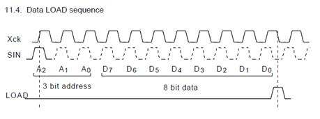 Pg. 9 of Datasheet. Loading one register. Pg. 9 of Datasheet. Loading one register.SIN has to first output the values of the address bit by bit then output the register values. After the last register value is set for one register, we have to assert load to be detected on the negative edge of XCK. All of this occurs 8 times since we have 8 registers. To provide the correct timing for all of this in setCamReg, we used the following timing diagram. 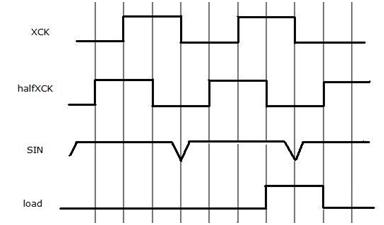 The timing diagram above shows the last 2 data values of SIN being set for one register and shows the load getting asserted when halfXCK is 0. We change the value of SIN at the negative edge of XCK to ensure that the positive edge of XCK will detect the correct value. Load is asserted when halfXCK is 0 to ensure XCK will detect Load on the negative edge. We implemented this using the following state machine. 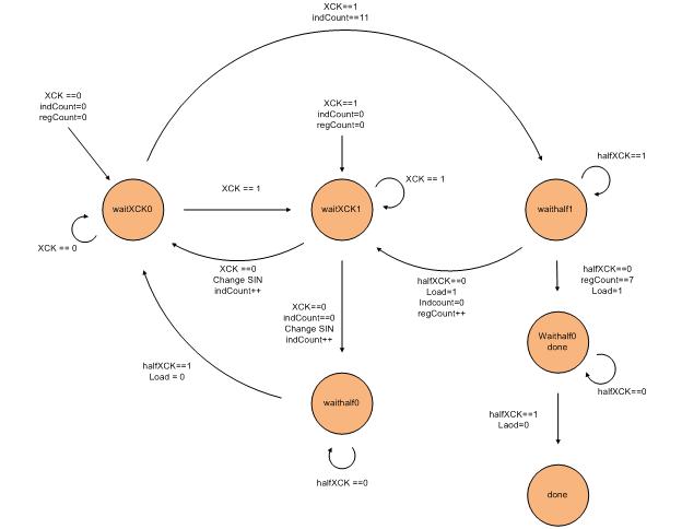 initStart The function initStart is used to send the start signal to the camera to start image capture. This function can only be called after we have called the functions camReset and setCamReg and this function should only be called once. The START input for the camera is an active high signal that needs to get detected at the positive edge of XCK. This is exactly the same as the camReset function except that Start is active high instead of active low. The timing and state diagrams are as follows. 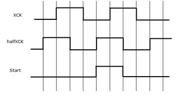 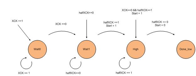 As seen, the timing diagram and the state diagram are identical to the camReset ones except that Start is active high.
camRead
The camRead function waits for a positive edge of the READ output signal from the camera and stores the value from the comparator into our array, Picture, using the function storePixel at every negative edge of XCK until we have stored every value up to and including the line number determined by the macro lastLine. Data is being fetched at the negative edge of XCK because the camera updates the output data Vout on every positive edge of XCK, so we fetch at the negative edge to ensure accuracy. We need to detect a positive edge because we need to know exactly what we are fetching. After read is asserted by the camera, the camera will output the frame pixel by pixel starting from the first line. The state machine for this function is the following. 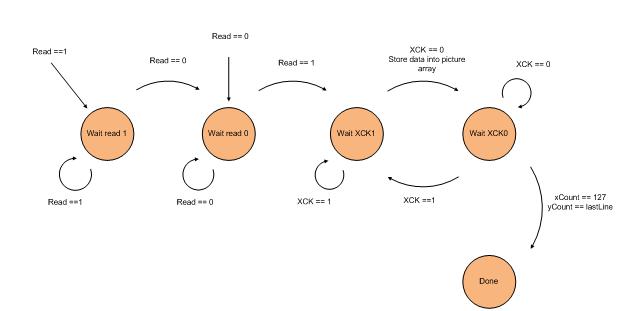 As shown above, we wait for the positive edge of Read, which is reached when we change from state Wait read 0 to Wait XCK1, and we continuously loop between the states Wait XCK 1 and Wait XCK 0 to detect the negative edge of XCK to store our data until we are finished. Algorithm When designing our algorithm to detect proper turning conditions, we had to consider various factors due to constraints presented by the microcontroller. Specifically, we want an algorithm thats accurate and precise, yet uses minimal processing time and memory. In the end, we want our algorithm to have the following properties. First, it must be as simple as possible. In order to minimize memory usage, the code should use as few variables as possible, and avoid arrays or large data structures. Also, the less code there is, the faster the algorithm will complete, reducing delay time between pictures. Second, the algorithm must be efficient. Our algorithm will not need the entire picture array to determine the proper turning condition. This allows us to exit camRead() as soon as we've sampled all the picture lines that we need. Finally, it needs to be flexible. The code needs to be easily adjustable for different lighting conditions and camera angles, which helps us debug and calibrate our car. Following these guidelines, the pseudocode for the turning algorithm is as follows. 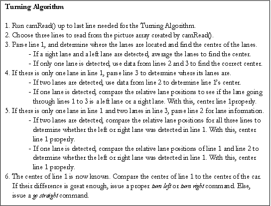 The algorithm is broken down into three main parts: finding a lane, finding the center, and issuing the turning command. Each part will be explained in detail in the following section. Finding a Lane Functions leftLaneLoc() and rightLaneLoc() return the relative positions of a potential left lane or a potential right lane, given a line number to parse from the picture array. The functions work as follows, assuming we are looking for a black lane on a white floor. 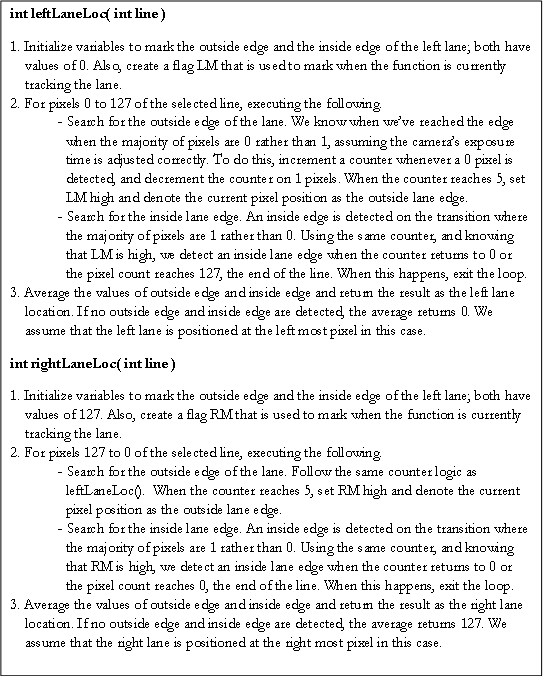 The lane finding functions follow a few simplifying assumptions. First, we assume that the picture taken will only show pixels of value 1 for the floor, and pixels of value 0 for the black lanes. Though the counter in the functions helps adjust for noise, we assume that we have chosen a proper camera exposure time that allows for proper contrast to detect lanes and lanes only. Also, the functions only finds potential left and right lanes; it may be true that leftLaneLoc() and rightLaneLoc() both detect the same lane as both a left and right lane. We left the centering code properly decipher this issue. Finally, The locations found for each lane is a relative center of the lanes, offset by some value due to the counter functionality. This offset may affect the accuracy of the centering code. Fortunately, since both the right lane and left lane have the same offset, the offsets cancel out if we average the left lane location and right lane location when we find the center.
Finding the Center
Following the algorithms pseudocode, we let the center of line 1 be the center on which we determine the turning condition for. In order to properly detect the center of a line when there is only one lane, we use 2 additional picture lines and their lane information to interpolate how the lane looks like, rather than inefficiently parsing through the entire picture array. To handle this task, we created a function called turningAlgoSimple() that returns a char representation of the turning state. The function works as follows, assuming the index for line 1 < index for line 2 < index for line 3. 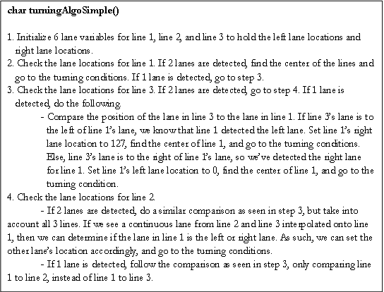 For this code, we make the following assumptions. First, we assume that line 1 is the furthest sample we care about, and line 2 and line 3 are points closer to the camera, hence the larger y axis offset. Second, we assume that all three samples are relatively close to each other. Doing this allows us to ignore some corner cases which would invalidate our algorithm. Also, it would be unnecessary to have too large of a line offset between 2 samples, as accuracy would not improve and the execution time of the algorithm will increase due to a longer camRead(). Finally, we assume that the offset used to determine the number of lanes detected is properly adjusted for the current camera exposure time and the camera angle. Issuing the Turning Command The function turningAlgoSimple() also handles setting up the correct turn signal for the MCU to output to the H-bridge. There are three proper conditions: turn left, turn right, and go straight. The H-bridge has two input ports to control the flow of the current: IN1 and IN2. To turn left, the port pin associated with the IN2 input is set high while the port pin associated with the IN1 input is set low. For right turns, the port pins values are reversed. To go straight, both pins are set low, meaning no current is sent to the servo motors.
Algorithm tradeoffs
Our current algorithm minimizes the amount of data needed to make a relatively accurate judgement of how to steer the car. This minimization also allows us to greatly reduce the time it takes to receive all the necessary image samples from the camera. Assuming there is a 25 kHz, the camera takes 0.630 seconds to take a 128 by 123 pixel picture, assuming a pixel arrives every cycle. However, if our algorithm only uses lines 20, 40, and 50, we only need to take a 128 by 50 pixel pictures. This will only take 0.256 seconds, which is a 59% speed increase. Since the algorithm code is lightweight, the bottleneck is at camRead(), so this speed increase allows for more samples and a better tracking of the lanes. Also, using less lines means that the picture can be much smaller. However, for more flexibility, we decided to keep picture array as its full size, since it only took about 52% of the 4 kB memory. In order to make it so lightweight, the algorithm is very specialized, and requires very ideal settings in order to work properly. Our main issue is that we have to assume that the exposure time is adequate for the entire duration of a drive; the algorithm cannot automatically adjust the exposure time of the camera if there is too much noise. This means that we cannot run our car in an environment with too much variation in light without manually configuring every different light scenario first. Timing constraints prevent us from implementing the automatic exposure time adjustment functionality. By the time the camera is properly reconfigured, the car would have most likely driven off a lane due to missed camera samples. Also, many corner cases are not covered by the algorithm. For instance, we dont check if the car is currently driving on a lane, of if the car ever drives off the track. Fortunately, the corner cases that are not covered should not arise, assuming the car starts within the track and the track is properly made.
Sample Camera Output and Algorithm Run
Below is an example execution of the algorithm on a pair of straight lanes with line samples at y axis offsets of 10, 20, and 30. The find location methods determine the proper left and right lane positions for line 1, and seeing that there are 2 distinct lanes, the algorithm calculates the proper line center. Comparing this center to the car center, it sees that the difference is within the go straight condition range, so the pins controlling IN1 and IN2 are both set low. 
Miscellaneous:
Macro explanations
We use the following macros to help simplify our code.
Our code uses the Timer 0 compare A interrupt to create the clocks that drive our camera and provide a hardware delay for our ADC distance sensor code. To do this, we create two clocks, XCK and halfXCK, where halfXCK is a phase shifted version of XCK by p/4. To do this, we let each interrupt trigger at a quarter of the total period. In the interrupt, we alternate between toggling the XCK and halfXCK. Doing this, the clocks will stay high for 2 interrupt calls and low for 2 interrupt calls, creating a complete clock period in 4 interrupt calls. Using a 20 MHz with no pre-scalar and OCR0A as 199, we see that the clocks have a frequency of 25 K. To insure that the distance sensor is sampled correctly by the ADC, we implement a counter that tracks the number of XCK cycles. The distance sensor code uses this counter to stall for the correct ADC values, waiting 4 cycles. This is more than enough time.
PuttyTestTask
To help debug our design, we created a simple putty terminal command interface using the UART, called puttyTestTask(). Within the terminal, we had the following commands.
The performance of our car is highly dependent on a number of factors that are discussed below: Friction: Starting the car moving, keeping the car�s rear wheels in motion, and turning of the car�s front wheels is heavily impeded by friction. Therefore, at times the car�s motion is sporadic tending to slow down when turning or speed up as the car gains more momentum. This occasionally leads to problems with the turning algorithm since if the car gains too much velocity, the algorithm computation does not complete in time for the car to react properly on a turn. Lighting/Color: Our car operates successfully when the lighting of the environment is consistent and there is no glare on the material that makes up the lines of the track. If there are any color inconsistencies on the track, accurate operation of the car may be hindered. In particular we discovered that the blue tiles that layered the floor that we initially tested on introduced artifacts into the images detected by the camera and corrupted the results of the turning algorithm. Once those colored tiles were covered up, the system worked properly. Hardware Limitations: The mechanical turning operation of our car was constrained to the specific car that we bought. Since the servo motors on the car only allowed for one turning angle of the wheels, this limited the ability of our car to maintain a centered position within the lane since it could only turn at one set angle. Instead the car tends to swerve within the lane as it navigates a road. This was an operation result that was expected. Sharp Road Turns: The car does not behave properly when it encounters turns on the road that are too sharp. This is due to the nature of how our image capture detects a physical area that is ahead of the car and how the image processing software requires time to determine whether to turn or not. With turns that are very sharp, if the car approaches quickly enough, the image processing software may not have detected the turn fast enough and when it does react it overshoots the line edge so the image captured is not reflective of the actual turn causing the system to not work properly. This was an issue that could not be easily fixed in software. Thus our system requires a track that has turns that are not too sharp. Overall the system works very well under certain constraints and demonstrates that a relatively small amount of computation can create a system that provides a vehicle with complex motor control that responds with reasonable reaction time.
Videos:
|
Electronics Project >